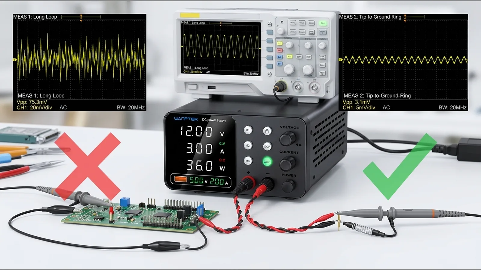
How to Measure Bench Power Supply Ripple and Noise Without Measuring Your Probe Loop
Before you trust any ripple or noise waveform on a bench DC supply, define the measurement bandwidth, the load conditions and the probe method. Without those three choices stated, the trace often shows the probe loop and instrument settings more than the supply itself.
Direct answer: define bandwidth, load and probe method before trusting the waveform
Treat every ripple or noise check as a stated method, not a single number on the screen. Note the oscilloscope bandwidth limit (or full bandwidth), AC or DC coupling, probe attenuation, ground connection style, and whether you are measuring at the supply terminals or at the load. Only after that setup is fixed should you interpret peak-to-peak or RMS readings. Guidance from Tektronix stresses that probe choice and connection technique strongly affect low-level results, so a tidy-looking waveform is not automatically a valid supply reading.
Separate DC level from AC ripple and random noise
The steady DC output voltage is not the same quantity as the small AC disturbance on top of it. Periodic ripple is usually tied to switching or rectification frequency; random noise is broadband and less orderly. Industry material on linear supply specifications describes this distinction and notes that PARD (periodic and random deviation) figures depend on bandwidth and measurement technique. When you discuss an example waveform, always state probe type, bandwidth, load and coupling so the reader knows which part of the disturbance you are looking at.
Use short probe connections and suitable attenuation
Long ground leads and large probe loops pick up magnetic fields and common-mode voltage, which can masquerade as supply noise. Prefer a short, low-inductance ground connection at the measurement point, and keep the probe tip close to the return reference you intend to use. For small ripple, lower probe attenuation generally helps preserve signal-to-noise at the instrument input; Tektronix measurement tips recommend low attenuation for ripple work, measurement as close to the terminals as practical, and low-inductance grounds to reduce error. If your only option is a long alligator ground lead, treat the result as provisional until you can shorten the loop.
Choose coupling and bandwidth deliberately
AC coupling removes the large DC offset so you can magnify the residual AC content, which is useful for ripple checks when the instrument’s offset range is limited. Bandwidth limiting can calm random high-frequency hash that is outside the band you care about; leaving bandwidth wide captures more of the noise spectrum but can also admit probe and environment artefacts. Probing application notes explain AC coupling, attenuation and short ground leads for low-level ripple work, and warn that the probe itself changes what you see. Decide coupling and bandwidth before you save a screenshot, and write those settings beside the result.
Measure at the output or load under stated conditions
Ripple at the supply binding posts can differ from ripple at the load after cables and local decoupling. State clearly whether the probe is across the output terminals or across the load, and whether any sense leads, remote sensing or extra filtering are in circuit. Do not connect a ground-referenced oscilloscope until you have verified the circuit reference and that the instrument and probe ratings suit the voltages present. A floating or differential approach may be required when chassis grounds are not common; never invent a “safe enough” shortcut.
Repeat with a known load and record the full setup
Use a documented resistive or electronic load at a stated current, allow the supply to settle, then capture the waveform with the same probe, coupling, bandwidth and ground method each time. Record instrument model settings at a high level (coupling, bandwidth limit, attenuation, measurement location and load), not marketing claims. Repeating under the same stated conditions is how you separate a real change in the supply path from a change in how you probed. Do not publish invented peak-to-peak figures, pass/fail comparisons or product-specific ripple numbers for any shop unit unless they come from an authorised live specification.
Common false readings and FAQ
Why does the trace look noisy with a long ground lead?
A large probe loop acts as an antenna. Shorten the ground path before concluding the supply is noisy.
Should I use AC or DC coupling?
DC coupling shows absolute level plus disturbance; AC coupling focuses on the AC residual. Choose deliberately and state which you used.
Does bandwidth affect PARD-style readings?
Yes. Wider bandwidth usually admits more noise energy; narrower limits can hide content outside that band. Always quote the bandwidth with the result.
Can I compare two supplies from casual screenshots?
Only if probe method, coupling, bandwidth, load and measurement point match. Otherwise you are comparing setups, not outputs.
Once you are comfortable with this method, you can review the live BenchPower Pro 3010 specification and 12-month warranty details on the product page—without treating any unpublished ripple or noise figure as proven for that unit.