Bench Power Supply Lead Voltage Drop: Why the Load Sees Less
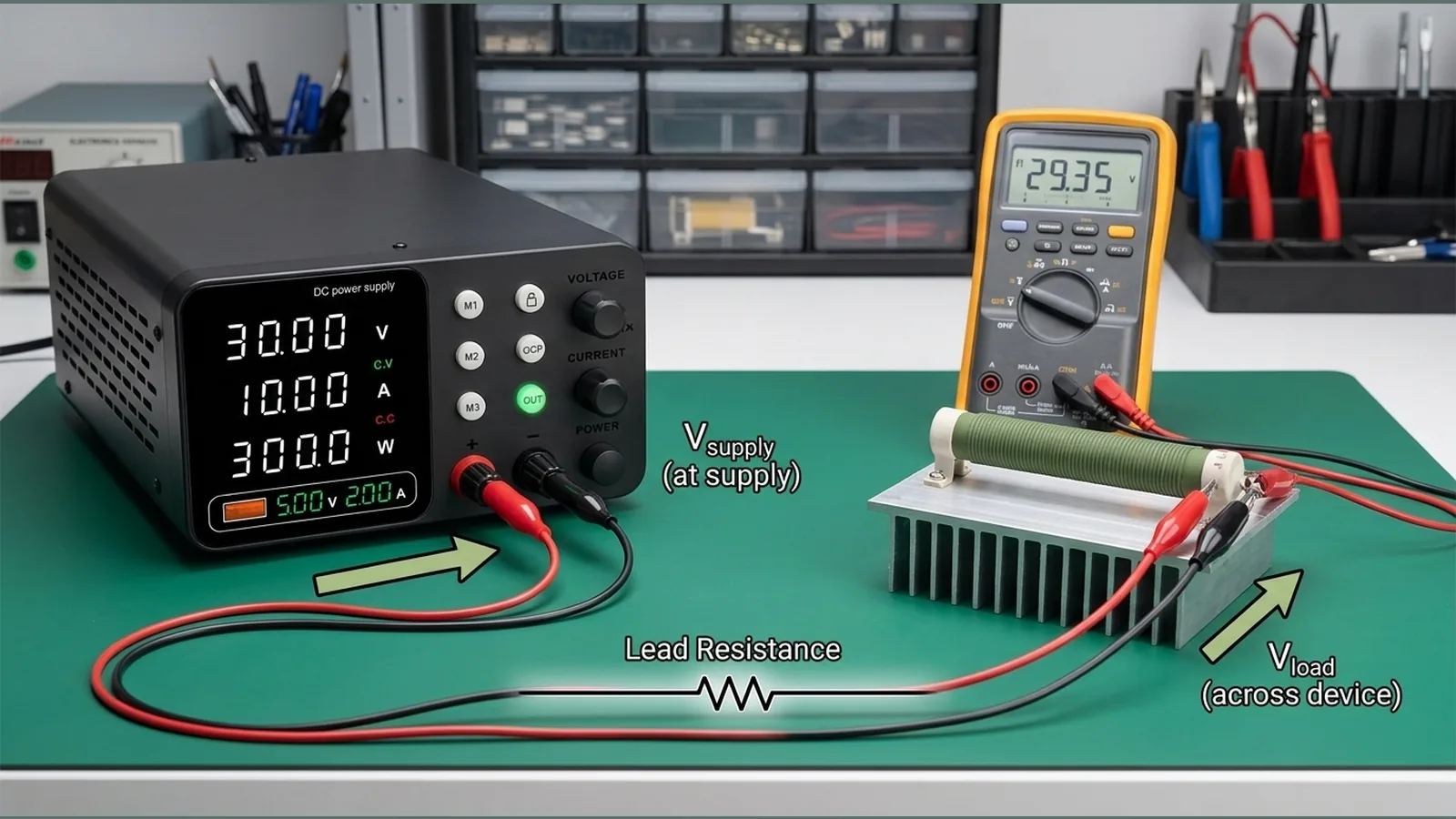
A bench power supply lead voltage drop appears when current flows through the real resistance of leads, clips and connectors, so the voltage at the load is lower than the voltage at the supply terminals. That difference is ohmic loss along the path, not a fault in the setpoint display alone.
Direct answer: current through real lead resistance creates a voltage difference between supply terminals and the load
When current leaves the supply, crosses each conductor and contact, then returns, every resistive element in that loop drops a small voltage. The supply may still show the voltage at its output terminals, while the device under test receives less. Industry primers on programmable supplies describe the same effect: voltage at the load can fall below the supply reading once current flows, which is why remote sense exists on instruments that support it. See the NI overview of remote sense, ripple and noise for that general explanation.
Measure at both ends under the same load
Confirm the drop with two measurements under the same load and the same lead arrangement:
- Measure at the supply output terminals (or binding posts) with the load drawing current.
- Measure again at the load terminals or pads, without changing current or connections.
The difference is the lead and connection drop for that current. Practical bench-supply guidance also stresses correct connection practice and measuring current carefully so load-point voltage can be assessed properly; see Keysight’s practical tips for bench power supplies.
How length, conductor size and connector condition change resistance
Lead path resistance rises when the conductor is longer, when the cross-section is smaller for the current in use, or when contacts are oxidised, loose, worn or undersized for the job. Extra joins, thin jumpers and poor clips add further resistance. None of these effects needs a special instrument feature to appear; they follow ordinary circuit behaviour.
UK safety guidance expects probes, leads, clips and connectors to be suitable for the work, maintained in good condition and chosen to prevent danger during electrical testing. The HSE guidance on electrical test equipment for low-voltage systems sets that expectation.
Use shorter or more suitable leads before raising the set voltage
Treat the wiring first. Prefer a shorter path, conductors and connectors suited to the current, clean tight contacts, and a tidy return path before you change the supply setpoint. Raising the set voltage to “make up” for cable drop can push the supply terminals above what the device can tolerate if the load current later falls or the path resistance changes.
Hard stop conditions remain: lead heating, connector ratings and the device under test’s maximum allowed voltage. Do not ignore warmth in leads or connectors, and do not continue if contacts are unsuitable or damaged.
What remote sensing does and when it is unavailable
On instruments that provide it, remote sensing measures voltage at the load and adjusts the supply so the load-point voltage tracks the programmed value more closely. It is a general instrument feature described by manufacturers such as NI and Keysight; it is not assumed here for any particular shop unit unless that unit is verified to include sense terminals or equivalent four-wire support.
If remote sense is unavailable, missing, unused or not verified on your supply, keep relying on local voltage measurement at the load and on improving the lead path. Do not claim or enable sense wiring without confirming the instrument supports it.
Avoid compensating past safe device voltage
Never blind-compensate by winding the supply voltage up until the load “looks right” on a meter at the far end while ignoring terminal voltage and device limits. If current drops, a previously “corrected” setpoint can leave excess voltage at the supply and at the load. Stay within the device’s safe voltage, respect connector and lead limits, and stop if leads or joints become hot.
Diagnostic table and FAQ
| Observation | Likely cause | Safer next step |
|---|---|---|
| Supply terminal voltage close to setpoint; load voltage lower under load | Lead and contact resistance under current | Measure both ends; shorten or improve leads and connectors |
| Drop grows as current rises | Ohmic loss along the path | Use more suitable conductors and contacts; re-measure at the load |
| Voltage recovers when current falls | Drop was current-dependent, not a fixed offset error | Do not leave an inflated setpoint in place |
| Warm leads, discoloured or loose clips | Undersized or poorly maintained connections | Stop and replace unsuitable leads or connectors before further testing |
| Sense terminals not present or not verified | Remote sense unavailable on this setup | Measure at the load; improve wiring; use confirmed details sense wiring |
FAQ
Why does the load see less than the supply display?
Because current through lead and contact resistance creates a voltage difference between the supply terminals and the load.
Should I raise the set voltage to cancel cable drop?
No. Improve the leads first. Blindly increasing supply voltage risks exceeding the device’s safe voltage when current or path resistance changes.
Does every bench supply offer remote sense?
No. Remote sense is only for instruments that provide and correctly use that feature. If it is not verified on your unit, treat load-point measurement and better wiring as the primary controls.
What else should I check on the leads?
That probes, leads, clips and connectors are suitable, maintained and selected for safe low-voltage testing, in line with HSE expectations.
For the current product details on the BenchPower Pro 3010 page, including the stated 12-month warranty term, see the BenchPower Pro 3010 product details.