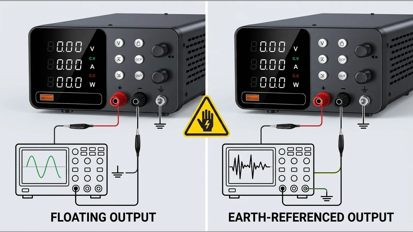
Bench Power Supply Floating vs Grounded Output: Check Before Connecting a Scope
Direct answer: floating and earth-referenced outputs behave differently, and the instrument manual controls permitted connections
A bench power supply floating vs grounded output question is settled by the instrument manual and by how the output return relates to chassis earth—not by terminal colour or a warranty period. Floating and earth-referenced outputs behave differently under load and under measurement; permitted connections are those the manufacturer documents. Before you connect an oscilloscope or any earth-referenced instrument, confirm the supply’s output reference and check continuity so you do not create an unintended earth path.
Define chassis earth, output return and a floating output
Three references matter on a typical bench supply:
- Chassis earth — the protective-earth connection bonded to the metal enclosure (where fitted), usually via the mains earth pin.
- Output return — the negative or common terminal of the DC output, which may or may not be tied to chassis earth.
- Floating output — an output whose return is galvanically isolated from chassis earth within the limits stated by the manufacturer; it is not the same as “safe to ignore earth”.
Tektronix distinguishes common and isolated output references and states that channel isolation and configuration must be checked for the intended circuit. Separate coloured binding posts do not prove isolation. For any shop unit, including models sold for bench work, do not assume floating-output or earth-binding capability; read the manual and verify continuity before use. A confirmed 12-month warranty is unrelated to grounding suitability and must not be treated as a safety proxy.
How a grounded oscilloscope can change the circuit
Most benchtop oscilloscopes have probe-shield (ground clip) paths that are earth-referenced through the instrument chassis. Clipping that ground onto a node that is not at earth potential can short part of the circuit through the scope earth, distort readings, or damage the device under test or the instruments.
Tektronix distinguishes ground-referenced and floating measurements and explains when a differential probe is needed for safe, accurate measurements. If the supply output return is tied to earth, or if your probe ground forces a second earth at the wrong point, the circuit you thought was floating becomes earth-referenced at that node. Never defeat protective earth, lift an oscilloscope earth lead, or make unverified series or parallel connections to “solve” the problem.
Comparison table of common measurement setups
| Setup | Output / probe reference | Typical risk if mismatched | What to verify first |
|---|---|---|---|
| Earth-referenced DC supply, single-ended scope probe | Output return and probe ground both earth-related | Unexpected shorts if you clip ground to a live node | Manual: is output return bonded to chassis? |
| Documented floating supply output, single-ended scope probe | Output return not bonded; probe ground still earthed | Scope ground can earth the return or a mid-circuit node | Continuity between return and earth; probe placement |
| Any supply, differential or isolated measurement path | Measurement path not forced through protective earth | Lower risk of earth loops when correctly rated gear is used | Probe/equipment ratings and safe system of work |
Treat this table as a planning aid only. Actual behaviour depends on the specific instruments and the circuit under test.
Pre-connection continuity and manual checks
Before applying power or connecting a scope:
- Read the supply manual for output reference, earth bonding options, and any isolation limits.
- With power disconnected and the unit unplugged where safe to do so, use a continuity or resistance check between output return and chassis earth (and between any earth terminal and the mains earth pin) as the manual allows.
- Confirm that test devices, probes, leads and connectors are suitable for the voltage, current and environment and are used within a safe system of work, as HSE guidance requires for low-voltage electrical testing.
- Plan probe ground points so they land only on nodes that are intended to be earth-referenced.
If the manual is missing or the continuity result is unclear, do not energise the circuit for measurement until you have competent clarification. Product pages such as the current product details are for commercial information; they do not replace the instrument manual for grounding decisions.
When a differential probe or isolated method is required
Use a suitably rated differential probe or another documented isolated measurement method when:
- you must measure a voltage that is not referenced to earth;
- a single-ended probe ground would bond two points that must remain separate;
- the circuit is mains-referenced or otherwise high-energy and a grounded clip would create a hazardous path.
Tektronix explains when a differential probe is needed for safe, accurate measurements on power-related voltages. Readers working on mains-referenced or high-energy circuits need competent supervision and suitable isolated or differential equipment. Front-panel terminals alone do not authorise floating the scope or removing protective earth.
Stop conditions and FAQ
Stop conditions
- Stop if you cannot confirm from the manual whether the output is floating or earth-referenced.
- Stop if continuity checks contradict the expected bonding described in the documentation.
- Stop if the only way to “get a waveform” would be defeating protective earth, lifting scope earth, or improvising unverified series or parallel links.
- Stop on mains-referenced or high-energy work unless competent people and suitably rated isolated or differential equipment are in place.
FAQ
Does a separate black negative terminal mean the output is floating?
No. Colour and physical separation do not prove isolation from chassis earth. Check the manual and continuity.
Can the warranty tell me the output is safe to float?
No. A 12-month warranty confirms commercial cover duration only; it is not evidence of grounding or isolation suitability.
What should I do next if I need the product details for this bench unit?
Review the BenchPower Pro 3010 product details, then still verify grounding and measurement setup from the unit’s own manual before connecting a scope.